 |
 |
|
|||


|
|||||
|
|
|||||
|
|||||||||||||||||
Selection of the correct Gaging (Gauging)
Product for
your Requirements
Introduction: This topic could take an entire book to fully cover all considerations but we will try to provide a basic common sense guide to selecting the correct type and resolution gage for your applications. Not every rule provided can be followed and there are always extenuating circumstances for every application. We will continue to add more information to this page as resources permit so as you review the page don't be discouraged if we have not covered all the possible topics.
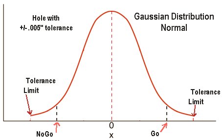
Attribute (Go & NoGo) Style Gaging
Unilateral or Bi-Lateral Tolerances ?????
Which Type of Gage Do I really Need ?
The Impact of Temperature on Gaging Results
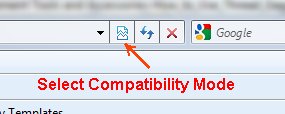
Having Trouble using the links above, change your Windows Explorer to compatibility mode
Gages or Gauges as you may prefer, can be grouped into several categories starting with Attribute or fixed limit or as most of you know them, Go & NoGo style gages, Variable Gauges, including Micrometers, Calipers, Dial or Digital indicator style and Electronic Style, then of course there is the CMM which we place in a category of it's own.
Each category has subcategories which we will cover briefly in order to, at a minimum, present the pros and cons of each gaging method.
Attribute lets you inspect the product for conformance but does not provide a measurement value for individual characteristics nor a running indication of your tool wear and process statistically. In most cases these gages will provide assurances that the product is functionally in compliance or not. Simple to use but need to be monitored for wear and damage.
Variable Gages will not provide confirmation that the product is generally functionally conforming but do give a measurement value that can be used to determine if a specific dimension is in or out of tolerance and by how much. These gages can have influences from the operator with items like a simple micrometer or can be complex and costly when a custom designed gage measures multiple dimensions and relationships all at one time.
CMMs or Optical
non contact measuring systems are usually used to qualify complex shaped parts,
verify first part compliance and most recently are being used close to the
machining process. They are normally slow and require complex programming so do
not lend themselves to simple attributes such as shaft diameters.
Many shop floor CMMs when used without temperature controlled and humidity
controlled rooms have a large measurement uncertainty so unless you have a very
expensive machine in a special room with good vibration isolation can and will
provide measurements with uncertainties of +/-0.003MM or greater. Some portable
CMMS have uncertainties greater than .001" for the measurement envelope. Optical
is another topic which we will cover separately. It is enough to say that
optical measurement is only as good as the surface finish and cleanliness of the
part measured not to mention the repeatability of part placement related to the
optics.
Attribute Gauges:
There are probably more Attribute gages in use in the manufacturing industry
than any other single type of gage except for maybe micrometers & calipers. The attribute
gage is a trusted method to measure a product's conformance to a tolerance and
in many cases is the absolute best method to confirm FUNCTIONAL fit.
Traditionally these gages come in pairs ( or should) with one called the Go and
another called the Not Go or NoGo member. As their names clearly define a part
in tolerance should fit the Go gage while not fitting the NoGo gage. ASME
clearly defines the tolerances for these gauges allowing a small amount of
encroachment from the gage itself on the part tolerance in order to assure that parts out of
tolerance will not allow the Go gage to fit in ( holes or internal threads) or
on ( external threads or male parts). These tolerances are established in the
industry and normally have a letter designation that will indicate the allowable
Gage Maker's Tolerance. Normally these tolerances such as ZZ, Z, Y, X, XX & XXX
for plain gages with common tolerance nomenclature of W and X used for Thread
Gages.
Usually the higher the letter in the alphabet the smaller the tolerance allowance.
Unilateral / Bi-Lateral tolerances . .
Even though I'm sure you already know these terms, bear with us for this brief explanation. Bilateral as its name indicates is Bi (both sides) when the allowable tolerance is split as in +/- around the nominal value. For instance Master Rings and Master plugs are made with their allowable tolerance split around the nominal. Example: A 1.000" master ring, class X, will be made to 1.000" +/- 0.00030".
These types of gages with Bilateral tolerances are normally called Setting Masters or just plain masters. They are traditionally used to set a comparative style gage, either a dial style gage like a dial bore gage or master an electronic gage that is made specifically for a part size or range of parts where the gage is not made with any sort of absolute encoder or scale like those used in a digital caliper. Not to say that these masters are not used to verify absolute gages like micrometers, digital calipers or even CMMs
Unilateral tolerances are exactly as the name indicates where the entire tolerance is in one (1) direction. An example of this is the traditional Go & NoGo plug gage set used to inspect a hole. In this case a 1.000" Go gage X class will be ground and lapped to .99994" while a NoGo of the same size of 1.000" will be made to 1.0006". Go Plugs are made to the "PLUS" tolerance and the NoGo Plug will be made to the "MINUS" tolerance. In this way you narrow your allowable tolerances just like establishing limits just inside your reject or scrap limits. Ring gages are the inverse with the Go ring made to a minus and the NoGo made to the plus. If the part fits in the NoGo it is undersized while if it will not fit in the Go it is oversized
Absolute or Comparative Gauging:
Lets start with basic definitions.
Absolute is considered a measuring system that does not require a
known master in order to set it up. For instance a 1" micrometer either
mechanical or digital provides an absolute reading by using the indications on
the barrel or using the digital display. The same fro a 6" caliper or more
basically a ruler. You obtain the actual absolute dimensions such as 5.006" from
the caliper or even a 6" micrometer. In the case of a 6" mic you make an
assumption that the reading is between 5" and 6" maximum but the readings on the
micrometer provide a definitive absolute number.
Comparative measuring devices on the other
hand always must have some sort of known part or master like a setting ring in
order to "Zero" the display whether using an analog dial , digital indicator or
some other sort of electronic display unit. These gages are often used in a
production environment when you simply need to know that the process is moving
and the part is getting larger or smaller and by a defined amount. Many of these
gages display either the absolute value (typically programmed into the
electronics) and /or the comparative value like +.00367"
or
-.00023".
Selecting the Gage that Best fits your Application
Answer the following questions:
1 Are you measuring the part as a process control strategy?
2 Are you measuring the product for final Quality or Functionality?
3 Can you adjust your machining process or tooling offset during manufacturing?
4 What is your tolerance?
Now that we have a few of the basic questions on the table lets see if they make sense. First we will deal with the simple solutions that dictate the type of gage required. If you are not going to adjust your machine tooling (in the cases of taps and dies, fixed formed tooling like grooves) you are not able to adjust individual attributes created by these types of tools so in most cases measuring the dimensional changes as the tool wears achieves very little. Cutting a thread with a tap for instance, does not allow you to change the PD nor the major or minor diameters (usually unless single point threading) so little is gained by accurately defining the exact PD of each part coming off the machine. The tool, tap or die wears out and you replace it. In addition if an economical method to inspect the functionality of the attribute such as a hole is required an attribute may be the most economical inspection method.
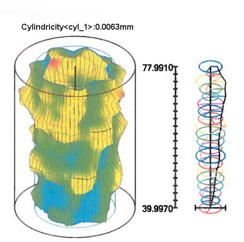
Functionality: I have used this term many times and don't want to assume everyone knows what we are referring to. Looking at the image below we see a hole that has been turned with what appears to be almost .0063mm of cylindricity. If we have a shaft that needs to slip in this hole then we have to take into account a functional measurement method that takes into account not only the diameter measured at some point in the hole but we also have to understand the shape error in the hole like taper, barrel shape ovality and roundness.
In order to do this you can measure the part with something like a Taylor Hobson TalyMaster which we whole heartedly support, or you can also inspect the parts on the floor with Go & NoGo pins that confirm the "Functionality" of the hole. It is always best practices to audit the actual form with a precision instrument like the TalyMaster but it has been an acceptable practice to confirm large production batches with attribute gages. No one solution is always perfect.
The SOLUTION is probably good for an Attribute Gage like a Go NoGo gage that checks the functional fit of the product before you ship it. Now the next step is what tolerance of Attribute Gage to choose. Talking about Thread Gages the choices are pretty much made up for you by established standards outlined in several different ASME specifications for Screw Threads so we will not go into these in detail.
As to traditional Go NoGo gages we normally recommend a simple rule of thumb that the gage should use no more than 10% of your tolerance in order to be most efficient. Example; we have a hole that has a +/-0.001 tolerance with a nominal diameter of 5.000". Using our 10% rule and after reviewing the Gage Maker's Tolerance charts we see that gages in the 4.510-6.510 range have a tolerance of 0.000065" for a XX class, 0.00013" tolerance for X class and 0.00019" for Y class and Z class tolerance will be 0.00025".
Which class is the most appropriate for this application? The obvious is the Y class at 0.00019 tolerance, however your particular situation may call for even a Z class ring which only uses an additional 0.00006" of your upper and lower reject limits. Using a Z class provides a bit more wear limit on the gage itself so it lasts longer and reduces your total range of parts that will be acceptable to this Go NoGo set to 5.00075" to 4.99925" effectively allowing a total range of 0.0015"
Using a Y class Go NoGo gage set will gage at 5.00081 to 4.99919 with an effective part range of 0.00162" instead of the 0.0015" of the Z class gages. When in doubt go to the front page and click on the Tolerance Chart.
Where we are going with this, is to make you aware that the highest class gauge is not necessarily the best most cost effective gage for the job. Take into account how well you hold your process and if the additional tightening of the tolerance boundaries by using a lower class gage can still achieve the results you need. In some cases, with very tight tolerances, you need the boundaries as wide as possible just to achieve your production needs. I did say that lower class Go NoGo gages impose a tightening of your part tolerance. That is because part of your part tolerance is given to the gage itself so is not available to you using this method. Think of these gage tolerances ( both the Plus and the Minus) as self imposed Upper and Lower control limits.
Roundness, Cylindricity and shape variations in the part also impact your gage choices. Using our previous example of a 5.000" part with only a +/- .001" tolerance can be complicated by variations in geometry such as roundness, taper and cylindricity to name a few. Example; the roundness allowance is .00005" (0.0013mm) while cylindricity tolerance is .00005" (0.0013mm). Now you have to consider that at the outer limits for each of these the part is still acceptable but by using the Z class ring we effectively now reduce the allowable tolerance spread by the worst case of these two conditions plus the gage tolerance allowance. The acceptable range of parts that the gage above (Z) class would pass assuming worst case for roundness and cylindricity can drop to 0.0014" or +/- 0.00007".
Nothing is just black & white but if you approach this task with a few weapons you can make good decisions regarding your gage selection when using Attribute Gauging.
Moving on to Variable gaging methods we have listed some of the more common measuring solutions.
Micrometers & Calipers (Digital and analog style)
Dial or digital (Digimatic) indicator style gages
Electronic column, or PC based gaging
Air Gaging Analog Display or electronic Display
Optical, Laser or non-contact gauging
CMM style (contact or no contact methods)
In general these methods fall into two categories. First being what we will cal Absolute and the second we will call Comparative style. Absolute type of gages like the CMM, Micrometer or Caliper type of gaging normally measure the part providing a reading with the whole number displayed. A 15" diameter part is usually measured with a display of 15.0000". The exception to that in this group is micrometers which are used with a predefined range like a 20" mic. In these units an absolute measurement is achievable by programming the absolute value, on some units, so that the reading, when closed is the minimum value the micrometer can handle. A 21" digital micrometer can read either in the absolute value (typically limited to programmable digital mics) or quasi comparative value (mechanical Mics) where the value is assumed to be 20" plus the reading shown. Digital calipers have similar features and usually read in absolute but some will allow a comparative reading (+.0125) as needed.
Absolute gages normally have resolution limitations even though improvement in the scales and encoders are continuing to improve these devices. Resolution is again like the the rules for selecting the G NoGo gages. If the resolution (we will cover accuracy eventually) is not 10 times better than the tolerance then you are not able to resolve the measurement to a point that it has value.
Controlling a process with +/-.001 using a micrometer with a resolution of .0005 is of limited value to you. The least significant digit is all important because the device, if analog, is not able to provide definitive graduations (you have to read between the lines) and to let you know it is only .0000 or .0005 out of tolerance. If using digital device with a resolution of only .0005" we usually show 0.0000 or .0005" when the actual measurement could be from .000449 to .000409.
Accuracy is another issue when using absolute measuring devices and is important. To give you an idea take any micrometer and review the small compliance certification that comes with them. You may see, depending on the manufacturer a statement of accuracy can state that the device is accurate to within +/- 0.00005" for instance. This normally indicates that readings thought out the entire measuring range of this device will be accurate within the values shown.
So should consider a measurement of your part with +/- 0.0002" tolerance with your micrometer that has an accuracy statement of +/-.00005" and resolution of .0001" valid?
Probably Not!
Understand that we all make compromises, but to assume the value you just measured with this tool shown in the example above will be accurate leaves you in a less than defensible position. I know some people will take exceptions to this statement and have been doing this sort of measurement for years using tools that we would not consider to have adequate resolution or accuracy. That is your choice. A device that can only resolve the least significant digit or .0001" ( is it a .0000 or is it a .0001") and already with an uncertainty of .00005" in accuracy is poorly equipped to define the size of the part with only a .0002" tolerance.
The point I want to make here again is to THINK! If you are working in tight tolerance areas remember the following, if you can not resolve it, the measurement is just a guess, if your measuring device is not accurate enough by the OEMs own standards and if you have not considered the impact of temperature on the part and also on the measuring instrument you will have your results questioned by your customer more than once.
(We will talk about thermal changes in parts and gages later).
You have to consider accuracy and resolution with absolute gages to determine if they are suitable for your job.
The CMM is no different and is normally used to measure absolute values and by using glass scales, or resolvers on some units, can act like a very large ruler to show the measurements of large or unusual parts. The CMM even those slated for shop floor use do have their own limitations. Most CMMs are certified to a volumetric error ( on many it is stated in U95). Primarily the CMM is a 3 axis complex CN type of device using glass scales in the 3 axis to take measurements when they are triggered by either the standard contact touch probe ( a very accurate light switch) or an optical non-contact sensor which provides the input for taking the measurement. For those who are not familiar, the CMM is given coordinates where it is supposed to find the part surface (your part program).
The head moves to that location and as it approaches some internal safety distance from the part surface programmed, it slows down and carefully approaches until a signal from the touch trigger probe or optical switch fires on contact. This switching action (usually repeatable to 1 micron) allows the CMM program to capture the scale readings and there you are a measurement value is created out of thin air.
Be careful when assuming that the CMM is the arbitration device for your measurement arguments. They are only as good as their accuracy/ repeatability statements. In many, the standard was +/- 3 microns (+/- .000120") so again tight work requires either a very special CMM like a Leitz or Zeiss or other high end machine installed in a temperature controlled environment to measure parts with tight tolerances accurately.
Comparative Measurement methods:
The last category we will cover here is the use and selection of when we refer to as a comparative gage. As the name indicates we are comparing. We compare a known part or master when we zero set the gage so that when measuring our part we visualize the differences we read between the part and master. Normally (not always) comparative gages are reading in when we will call deviation form nominal. This method is used when the gage is controlling a process on a shop floor and all the information we need or is it bigger or smaller than our mean target so we can adjust the machining process.
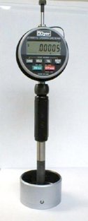
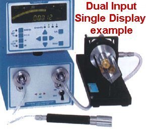
Examples of this are as simple as a dial indicator in a height stand, A snap gage with dial or digital display, special fixture using indicators, or gaging electronics like a Marposs Merlin or Mitutoyo Digimatic indicator, Western Gage Micro II with air ring, Dyer 240 series Bore Gage or a Mahr Federal Dimentron plug.
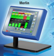
Photos provided by Marposs Corporation, Western Gage Co. and Dyer Corporation
All of these gages need some sort of qualified setting master or part that has a known value that can be used to set our gage to. They offer some advantages and disadvantages. Disadvantages are that they have to have a qualified (certified is best) master, their measuring ranges are usually limited and in many cases they are not as flexible so may actually be built to a dedicated part or family of parts.
Advantages are multiple in that they are usually fast, less subjective (no feel required) can have very high resolution like the .000005" resolution of the Western Gage Micro II air gage instrument and in a lot of applications can be robot operated or loaded like the Salem Design & Manufacturing Universal Inspection System. For larger parts they can be less bulky and for complex parts multiple measurements can be made based on the design of the gage simultaneously.
These style of gages may use analog or digital indicators, LVDTs, linear scales or other methods to transmit the differences in the part size to some sort of display. Displays can be as simple as the face of a dial indicator or as complex as a PC with multiple measurements shown simultaneously on a single display.
For those of you with wide open tolerances this section has little relevance in what you are doing. However for those of you working with tolerances under .0005" ( 10 microns /.010mm) you need to at least consider the impact of part temperature and also just as important the thermal influences of the gage itself.
TO BE CONTINUED: We will elaborate on this and many other topics in coming additions. Issues like thermal impact of the part, the gage itself, inspection gages versus gages for process control, optical and laser gages and how they work and more.
working
Back Home
Back Home
Go Directly to the Web Store Back Home
NOTICE: All information provided on this reference sheet is intended to be for general guidelines and may not represent the full
specifications or instructions as outlined within ASME requirements or other technical specifications which govern the manufacturing and use of thread measuring gages.
thegagestore.com/LEECO INC, does not represent this information as anything
except a common sense general set of guidelines. You must always follow
the technical specifications relative to the gage, thread design or
other related gage attributes and usage that apply. When in doubt always acquire
the current specification from
http://www.asme.org/ codes & standards.
IF YOU
HAVE QUESTIONS OR COMMENTS, E-MAIL
Technical@thegagestore.com
OR FAX US AT 860-404-8903
![]()
![]()
![]()
![]()
![]()
![]()
![]()
Copyright © 2001-2007 All Rights Reserved
Read
our security and privacy polices
E-Commerce Designed and Hosted by
SYO Computer
Engineering Services, Inc.
![]()